|
The high sensitivity of a thermistor
makes it an ideal candidate for low cost temperature
measurement. One of the simplest applications is placing
the thermistor in one of the legs of a wheatstone bridge.
Substituting a second thermistor for Rx (fixed resistor)
makes the circuit twice as sensitive, permitting the
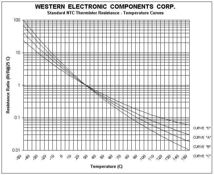
use of a lower sensitivity meter. Because the resistance
vs. Temperature characteristic to the NTC thermistor
is nonlinear, it is often advantageous to lineraize
the curve. A simple voltage divider tends to linearize
the output voltage as a function of temperature, while
a single parallel resistor linearizes the resistance
vs. Temperature curve. In each case, the maximum linearity
error is a function of the length of the temperature
span. For spans of less than 50 C, a single resistor
can linearize to better than +/-0.5 C accuracy. Decreasing
the total linearity error can be accomplished by using
more than one thermistor in the network. If the temperature
span is relatively short, it is also possible to improve
accuracy by using a single thermistor in a series/parallel
resistor network.
THERMAL
TIME CONSTANT
The thermal time constant is an indication
of the time that component needs to reach thermal equilbrium.
This constant depends on two important parameters. One
is the thermal capacity (H) of the component, the energy
that must be applied to the component in order to raise
its temperature by 1 Kelvin (or the energy that the
component must lose in order to lower its temperature
by 1 Kelvin). The units are thus quoted in Joules /
Kelvin. The second parameter is called the dissipation
factor. If the temperature of a component rises, it
will tend to dissipate energy. This dissipation will
depend on the surroundings and also on the component
itself. The dissipation factor is defined as the ratio
of the change in power dissipation with respect to the
resultant body temperature change (units in W/K).
TEMPERATURE
MEASUREMENT AND CONTROL
When used in conjunction with an amplifier,
the thermistor provides a low cost means of achieving
highly reliable temperature control. The system can
be simple as the on/off control of a transistor driving
a relay or as sophisticated as a closed loop proportional
controller. The thermistor's main asset in temperature
control applications is its high degree of sensitivity.
At 25 C a typical NTC changes about -4.4% in resistance
for a 1C change in temperature. Using thermistors, temperatures
have been controlled to better than 0.001 C.
NTC INRUSH CURRENT LIMITERS (ICL)
Inrush current limiters are used to solve
the problem of current surges in switch mode power supplies.
The current surges are created by large filter capacitors
used to smooth the ripple in the rectified 60Hz (50Hz)
current prior to being chopped at a high frequency.
The relatively high initial resistance of the thermistor
acts to limit the inrush current until the power it
is dissipating heats it to a high temperature. At this
high temperature, the very low resistance of the thermistor
effectively removes it from the circuit. A typical switch
mode power circuit is illustrated below.
|